
Mark Lancaster is a Product Support Specialist with the Synergis Engineering Design Solutions Helpdesk team working to support customers to create data-rich designs and efficient workflows. There you have it, a workflow that allows you to take 2D geometry and a 3D part from it.


Autocad 2d to 3d converter online update#
Now when I return back to Inventor, a red lightning bolt is present next to the (imported) drawing in the browser and the update icon is lit.I’ll scale the drawing based on the origin (0,0) point and the other thing I will do is move the entire drawing so one of the connector ends is setting at the drawing origin point.In order to change the drawing scale I will need to open the 2D drawing file directly in one of the AutoCAD platforms.Īlthough I’m using AutoCAD 2016, the drawing can be modified in any version of AutoCAD as long as it’s able to open it. If I check the overall length of my revolved extrusion, you will notice the scale of the imported drawing is not at a 1 to 1 scale.Now let’s revolve it and save the part file.Next I will finish up my sketch by creating the missing geometry that will form the revolved extrusion.I’m also projecting the ends of the connector as construction lines in order to determine my axis of rotation. Since I planned on making a revolved extrusion of this part, I will only project a certain amount of the 2D geometry.Select the drop down under Project Geometry and pick Project DWG Geometry Now we need to start projecting the drawing geometry that will make up our sketch.Create a 2D sketch on the same work plane that was used when importing the drawing.From there I can use the rotate triad method and turn my drawing 90 degrees. To reorient (if needed), right mouse click on the drawing in the browser and select Translate.For the scaling aspect, I will cover that shortly.At this point the drawing may be inserted at the incorrect orientation and/or wrong scale.The drawing should now appear on the work plane you selected earlier.Accept the message about the file not being saved and/or about the associated underlay that’s being created.This point will match the (0,0) location on the drawing.Select the point (origin or 0,0) where the drawing will be inserted.Select on of the work planes to place the drawing.At this point the drawing you’re importing should be placed somewhere in the active Inventor project area.Navigate to and select (open) my 2D drawing.Next, select Import located under the 3D Model/Create ribbon section.For my configuration, no new sketch is created when I start making a part. For example, let’s say you only have access to a 2D drawing file of a stainless steel barbed connector from McMASTER-CARRįirst let’s start out by creating a new part in Inventor 2016. Granted there are a few workflows out there to take 2D geometry and make a 3D model from it, but with the release of Inventor 2016, it just got easier. So what steps did you take to convert their 2D drawing over to 3D?

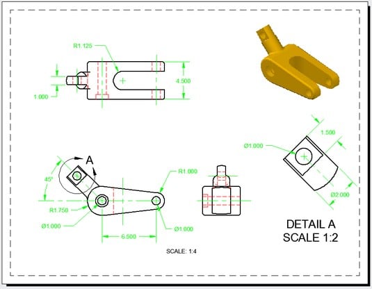
Have you ever contacted a vendor requesting a 3D model of their product and you only received a 2D drawing of it? I will even bet the drawing you received had limited amount of information on it as well. By Mark Lancaster, Synergis Engineering Design Solutions


 0 kommentar(er)
